Constructing
a dimmer for your Anton
Bauer®
Ultralight 2
From the
Poor Man's film & video equipment construction series
Copyright © 2005 - 2017 George Odell All
rights reserved
Background:
If you can wire up a rather simple electronic circuit (or know someone who
can) you can construct this neat little Poor Man's $25 lamp dimmer for your
Anton Bauer® Ultralight 2 camera light that will allow you to go from
full on to almost off. Why would you want to do that? Because then you can
put in a higher wattage lamp than you would normally use and dim it down
to any lower level to match your shooting situation. Believe me, once you
try shooting this way you'll wish you had done it sooner. BTW: While I made
this dimmer specifically for the Ultralight 2 I happen to own, the same exact
circuit can be used with any other 12-14 volt DC video light (ie: Frezzi
Mini-Fill, Cool-Lux Mini-Cool, etc.) up to 65 watts.
Again, the premise here is to use a larger wattage lamp so that you can dim
down to the exact level you're working at. My feeling has always been that
on-board camera lights should be invisible to the viewer. That is, they should
provide an eye light or some modest fill on the subject but they should not
be so bright as to call attention to the light source. For me, up till now,
this has meant using a 20 watt BAB and watching how close I got to the
subject since I had no control over the light level. Sometimes I would even
tilt my Ultralight up a bit so only the rim of the light was hitting
the subject. Recently I added the AB soft box which works just great, but
also cut my light level way down. I realized the ideal solution was a brighter
lamp and a dimmer to control it. Hence, the project you see here came into
being.
The circuit, though modest in its design, is a true PWM or Pulse-Width-Modulation
lamp dimmer just like the big boys sell. Basically, it triggers the MOSFET
(the lamp controlling device) on and off like a switch at a rate of around
29,000 times per second while allowing you to manually vary the duty cycle
to control the ratio of on time to off time. The lamp is always
getting full power, but for greater or lesser amounts of time. Therefore,
it can be dimmed without affecting the color temperature too greatly. This
is very important to us video folks. In fact, using this dimmer you can go
from the 50 watts of an EXN down to the 20 watts of the BAB and only cause
a shift of around 100 degrees Kelvin (3,000 to 2,900)! What you'll have is
almost three times the available light at your finger tips by working at
50 watts as opposed to only 20 with the added benefit of every wattage
in between.... thanks to the precise control afforded by the dimmer.
You'll have to allow me to digress from time to time to fully explain the
electronic theory used in this circuit so that those that do understand can
fully appreciate how it all works. That said, you do not have to completely
understand electronics to build this project, but you should have a working
knowledge of basic circuit assembly techniques.
How to construct
a dimmer for your Anton Bauer® Ultralight 2:
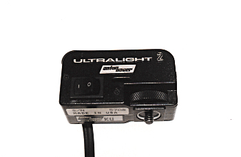
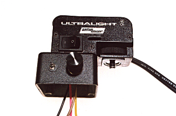
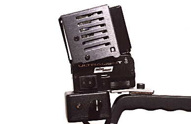
| Here's the little bugger all folded up in it's fetal position. As someone
who can appreciate good product design I have to hand it to the folks at
Anton Bauer®. The Ultralight 2 is a model of a well thought out, carefully
planned design implementation. Take a close look at yours and I think you'll
agree with me. If this product did not win any industrial design awards it
certainly should have.
Now before you proceed any further you should know that what you are about
to undertake will certainly void any warranty you may have left on your unit.
Manufacturers take a dim view of anyone drilling holes in what they make.
Please also understand that this modification is done at your own risk and
is not in any way sanctioned by Anton Bauer®. If you're still game, then
let's go! |
 |
 |
There are six phillips-type flat head screws that hold the two side panels
of the Ultralight to the main body. Remove them now and store them away for
safe keeping. When this is done you can pry apart the panels only a tiny
bit. You will also need to remove the strain relief securing the power cord.
This is done using a pair of pliers. Grab the back of the strain relief (the
back being where it is exposed on the outside of the panel) tightly and squeeze
the pliers to compress the two halves. You can now pull back on the strain
relief and remove it from the hole in the panel. When it finally pops
free pull the halves apart and remove it completely from the cord. Put this
away with those six tiny screws. This side panel is now free and clear (as
shown on the left side in the photo) and you can slide it down the cord out
of your way for the time being. You now have access to the other side panel
holding the switch in order to work on the wiring modifications. |
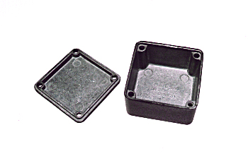
| I used the smallest cast aluminum casing Hammond makes for this project.
Measuring around 2" by 2" by just over an inch deep it makes for a neat and
very rugged housing for the electronics. I used their black painted casing
to match the color scheme of the Ultralight. This is actually the most expensive
part of the whole project at around ten dollars from Mouser Electronics.
BTW: If you don't know them, Mouser Electronics is a huge supply house out
of Texas that sells just about everything in electronics for industry as
well as the hobbiest. All the major components used in the dimmer project
came from them and I've provided the Mouser part numbers on the schematic
diagram for easy ordering.
Mouser Electronics is at
www.mouserelectronics.com.
|
 |
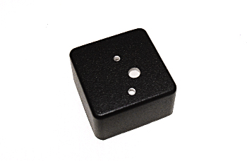 |
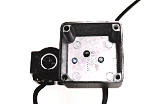
 Looking
down at the top of the casing you can see I've drilled three holes. The two
smaller ones are 1/8" diameter to accommodate 4-40 x 1/2" long screws. These
will secure the case to the base of the Ultralight. The larger hole is 1/4"
in diameter. It's offset a bit to allow for a clearer pathway for the four
wires that will extend down from the Ultralight and into the casing. If you
scan down the photos you will see you need to move the casing out a bit to
allow clearance for the Ultralight's mounting screw. Looking
down at the top of the casing you can see I've drilled three holes. The two
smaller ones are 1/8" diameter to accommodate 4-40 x 1/2" long screws. These
will secure the case to the base of the Ultralight. The larger hole is 1/4"
in diameter. It's offset a bit to allow for a clearer pathway for the four
wires that will extend down from the Ultralight and into the casing. If you
scan down the photos you will see you need to move the casing out a bit to
allow clearance for the Ultralight's mounting screw. |
| After I drilled the holes in the casing I transferred them to the bottom
of the light base. I then drilled into the base of the Ultralight using the
same diameter drills. This is made of rather soft plastic so go nice and
easy on the drilling. In this photo I'm just making sure that the screws
line up before going any further with the wiring. |
 |
 |
This is a side view of above. You can see the casing will stick out past
the front of the base by about 7/16". The two 4-40 nuts can be seen inside
the base securing the screws.
 When you have
this section completed you will need to remove the casing so you can safely
drill the holes for the dimmer control pot and the LED. When you have
this section completed you will need to remove the casing so you can safely
drill the holes for the dimmer control pot and the LED.
Here is the drilling guide I used to mount the LED and pot to my project.
The .25" hole for the LED assumes you use one of those cheap plastic mounting
kits that usually comes supplied with the individually packaged LED's. I
buy my LED's in bulk now but I still have drawers full of these mounts. |
| The electrical wiring modifications are very simple and involve the
connection of four #18 gauge wire leads. This is clearer to understand by
looking at the top section of the schematic diagram... the stuff above the
green line. You will start by cutting both sides of the power cord in the
middle of the heat shrink. Solder a new red lead to the positive side of
this cord and a black one to the negative side. If your light has the AB
power tap (D-type) connector it is clearly marked + and - on the side. If
you have some other type of battery connector you will need to determine
the correct polarity before proceeding. Make sure you get this right or the
dimmer will not work. After you have added these new leads and applied new
heat shrink you can reinstall the strain relief to the power cord. Next you
will need to connect a lead to the side of the switch that is now free and
another lead to the side of the lamp wire now free. Any color will do since
it does not matter how these last two leads are connected. Either direction
will work, here. Heat shrink these as well and run them down through the
1/4" hole in the bottom of the base. It should now look something like what
I have in the photo. |
 |
 |
The dimmer control pot and the power on LED have been mounted
to the same side of the casing as the lamp on-off switch. The side that faces
you when it's on the camera. The pot also contains the power switch for the
dimmer circuit. Although the circuit draws very little current when the lamp
is switched off, being able to unpower the dimmer when storing the camera
is required to avoid any unnecessary drain on the battery. The LED simply
tells you the dimmer is powered up so you can make sure to turn it off at
the end of the day.
Another feature, here, is the ability to preset the dimmer control to a
particular level and leave it there and then use the Ultralight's power switch
to turn the lamp on and off. |
| An underside view of above with the LED and pot in place and the leads
coming through from the power cord and lamp. What looks like lots of free
space will be filled up pretty soon when we get to the actual dimmer circuit
construction.
Take a look at the dimmer schematic diagram, below. Everything below the
green line must be housed inside this little casing somewhere. It will all
fit if you take pains to construct the circuit board carefully, as I've done. |
 |
| What you're looking at, above, is called a PWM or Pulse Width Modulation
dimmer circuit. It uses an NE555 timer IC configured as an astable multivibrator
with a variable duty cycle. The switching frequency is centered around 29khz.
in order to keep the filament oscillations inaudible but still remain below
the threshold above which the MOSFET will be overclocked and require more
extensive heat sinking. The component values should be identical to those
used here in order to obtain the exact same switching rate. The MOSFET chosen
is overrated for the job it is to do for both long life and low heat.
The 5 ampere Miller hash choke, acting as the power supply line filter, provides
a theoretical limitation of just over 62 lamp watts for the specified inductance.
However, you can safely use any lamp in the MR-16 series up to 65 watts.
With the choke in place, as shown, there will be a residual noise level at
the battery terminals of approximately 60 mv. (.060v) P-P at the switching
rate. |
 |
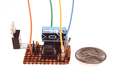 |
Nope, that's not one of those large trick nickels. Other than the line
filter, the pot and the LED this is the entire dimmer circuit. I used a small
piece of breadboard to mount the components. I have a few steel terminals
towards the back to solder the larger #18 gauge leads to. I always find it
a good idea to use DIP sockets for mounting IC's to prevent damage from the
soldering. The MOSFET on the left side has been mounted to the board such
that it will be against the adjoining casing wall. This will act as a heat
sink for the MOSFET. You must use a standard TO-220 insulator kit (mica insulator
and nylon flange washer) to secure it to the side. I used a flat head 4-40
1/2" long screw counter sunk to be flush with the outside wall. Apply some
heat transfer (thermal) grease to the mica insulator on both sides.
BTW: Those parts I have not provided part #'s for are common "junk drawer"
components that most hobbiest-types will have just lying around. If you have
any trouble finding them at Mouser let me know and I'll be more specific
in the next update of the article. |
| On the far right you can see the MOSFET bolted up against the inside
of the casing. The circuit board is located at the bottom and is mainly held
in place by the leads of the MOSFET and further secured with some double
sided foam tape. The hash choke is that large tubular thing with the copper
windings around it under the yellow and reddish/pink leads. I've sealed mine
inside of some clear heat shrink to keep it electrically insulated from the
back terminals of the pot's switch. If you find the control knob has the
lamp fully on when just past the switch-on position it means you have the
two diodes (1N4001) reversed. Just switch their polarity and you'll have
the lamp at it's lowest setting counter clockwise on the far left and maximum
brightness when fully clockwise on the far right.
Warning: Use some other 12v DC source to test the completed project. A
power supply or a fused 12v lead acid battery. Do not test using your nicad
camera battery. If you have a short somewhere, and you probably will, you
can damage your battery for good. |
 |
 |
With the bottom cover in place this is what the final project will look
like. I used a narrow body Alcoswitch knurled knob with an anodized black
finish. It's a $5 part that may be overkill but does look and feel very nice.
A little class can't hurt.
BTW: The PWM circuit will cause the lamp to only consume enough current to
drive it at any given level. There is no wasted battery power when using
settings less than 100% full on. Running your lamp at a level of around 20
watts (like that of a BAB) will only use up 20 watts of battery power. |
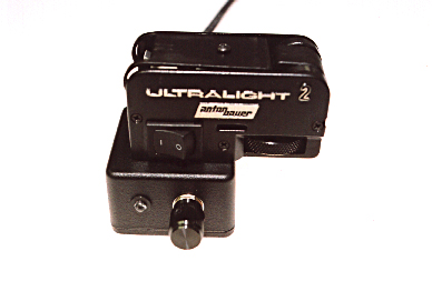
| Adding the lamp module it looks like this. As you can see I have also
constructed a small angled bracket to secure the Ultralight to the top of
my Beta SP camera handle. The bracket aims the light down much lower than
the unit can reach normally. This lets me center the height of the light
better when shooting subjects closer to my camera lens. The lamp module will
easily tilt up for longer light throws. I had actually been using this for
several years prior to adding the dimmer so I did not have to change how
I was mounting the Ultralight. You will no doubt need to come up with something
similar to meet your specific camera mounting needs. I also have
another version of the bracket for my DVCAM that looks like the letter
Z as if you grabbed it at both ends and stretched it out. Up and
out...get the idea?
Both brackets are made from 7/8" wide by 1/8" thick steel that was purchased
in a three foot long bar from Home Depot for a few dollars. The right-most
side has a 1/4" hole to accommodate the hex bolt securing it to the handle
and the left side was tapped for a 1/4-20 thread to accept the mounting screw
of the Ultralight. I also glued a small piece of rubberized cork under the
bracket on the camera handle side to prevent scratching. You can purchase
this in short 10" wide rolls at any auto supply store. It's used for making
gaskets. |
 |
 |
Remember that Anton Bauer® soft box I mentioned at the top of this
article. Well, here it is on my camera. What a package I have, now. Soft,
even light at any level I will ever require at the touch of a control. I've
pretty much standardized on the EXN 50 watt MR16 flood lamps. While Home
Depot sells the Sylvania brand in packs of three for less that $10, I've
found the best EXN lamp is made by GE. They have a slightly wider spread,
shine a bit cooler at 3050K and have about a 13% higher candle power
than the other brands*. They also claim to last
longer than other lamps at 6000 hours on average**.
They'll run you $5 a piece at Bulb Connection
(www.bulbconnection.com).
BTW: Ushio now offers their EXN "Whitestar-brand" lamps in both 4200K and
5300K color temperature for around $7 from Bulb Connection. Their 4200K version
would be useful for shooting under daylight white florescents without the
need for a blue filter. I have tried these and found there is only a slight
advantage light output wise... i.e.using the EXN "4200K" lamp -vs-
adding the 3204 blue filter. However, they would seem more convenient to
use than trying to slip a piece of gel between the lamp and the heat shield. |
Finally, some of you may have the Automatique® feature on your AB camera
mount that switches the power tap (and thus the camera light) on and off
with the camera run switch. You can rest assured the Poor Man's dimmer will
work with this system with no problem. Happy shooting and please write to
me when you have yours built to tell me how you like using it! Your feedback
(positive or negative) makes this all worthwhile.
This construction project article is Copyright © 2005 - 2011,
George Odell. All rights reserved. Neither the text, the pictures, the graphics
and/or the site itself may be copied or mirrored on any other web site. You
are welcome to link to this site and for that, I thank you.
If you find this article copied or mirrored on any other web site or being
sold electronically as an email or as part of a CD or in a paper manual,
please let me know. I spend a great deal of time creating these how-to articles
to help others and I take a dim view of folks who would try to profit from
my efforts. Copyright violators will be prosecuted to the full extent of
the law.
Addenda:
* In my tests I found the GE to light a circle
34" in diameter at a distance of 32". The Sylvania lit a circle only 29"
in diameter at the same distance. Also, there was a noticeable dark spot
in the center with the Sylvania that was not visible with the GE. Close up,
the results were similar. At 6" the GE produced a circle 5" in diameter while
the Sylvania's was only 3.75" at the same distance. This factor alone would
make the GE the preferred choice when using the Anton Bauer® softbox.
** The actual life of the MR16 halogen lamp will
be shortened from it's theoretical life span due to the fact that we are
dimming the lamp. Halogen lamps have a cycle whereby the walls of
the glass bulb are kept clean through a continual process in which the halogen
gas combines with the evaporated tungsten atoms removing the darkening deposits.
As the two come into contact with the hot filament the tungsten is separated
from the halogen and the process repeats. Now in order for this to work
effectively the operating temperature of the lamp must remain around 250C.
Dimming the lamp below 70-80% lowers the temperature and the process will
not complete the cycle. Some of the resulting blackening can be partially
reversed if the lamp is operated at full power periodically to allow the
halogen gas to remove some of the deposited tungsten. However, for our needs,
replacing the lamp every few months is probably not a bad idea and will
insure a fresh, clean bulb.
Poorman's HMI
(sort of) solution for your Ultralight kit
If you're like me and sometimes find you need to punch in some daylight on
your interview subject I have a solution you can try. I scoured the
list of possible MR-16 lamp choices and found one, the FPA Titan made exclusively
by Sylvania that puts out an intense 14,000 candle power beam at around 10
degrees from a 12 volt source. It's rated for 65 watts which makes it perfect
for our little lamp dimmer project. What I did was locate a piece of dichroic
glass from an old Colotran filter. It was much larger than I needed so I
had a local glass cutter cut in down to 2" by 2". I then removed the clear
glass heat filter from another Ultralight head module I had purchased on
Ebay. I mounted the dichroic filter in it's place using some Permatex black
silicone adhesive sealant, remembering to mount the filter so the gold side
(the coated side) was facing the lamp. I popped in my FPA Titan lamp, got
out my light meter and set about to make some measurements. What I found
was I could get a very respectable 290 foot candles at a distance of 5'.
At 4' the level jumped up to 410 foot candles and at 3' it was a blistering
750 foot candles. The beam is rather narrow giving only around a 10-12" spread
at 5' but that should be more than enough to cover a reporters head... unless
he has a fat head.... but I digress. For me, I can see using this to fill
in faces when I shoot under a tree, or on a cloudy day, or inside a car.
I can probably even use it to fill in a face that's backlit from an office
window. BTW: There are other FPA's made by other manufacturers but they will
have less output than the Sylvania Titan. I found them for around $17 at
Bulbconnection.com. Manufacturers #65MR16Q/10/NSP/T. Yes, I know Anton Bauer
makes a dichroic filter on a swing out door for around $100 and that should
work just fine. Having the filter inside as part of the head module is just
neater, that's all. BTW: Don't even think of using a piece of gell for this
application... for two reasons. First, the beam is so intense it will burn
through the gel is seconds. Second, blue gel eats up too much light output
(lumens) from the lamp since it is absorbing the light rather than
band-passing a given wavelength like the dichroic filter.
Using the internet
to file news stories
This article might as well be called the
Poorman's Satellite
Solution. This is a system we are now using to get broadcast quality
video from a location field shoot to a client, network or
television station. We offer it up for others who may be considering
doing the same thing. Low in cost and easy to set up in keeping with the
Poorman's tradition, of course.
If you found this article informative or at all useful,
drop me a line and let me know!